 The manufacturing documentation necessary to perform the assembly service and the eventual completion of components consists of several documents including.
Bill of material
It is a document containing all elements with their quantity and other parameters, whose assembly and / or completion is to be done.
Main recommendations for the correct implementation of the BOM:
- recommended format: excel;
- BOM table should consist of following elements:
- number of elements on one PCB,
- element type, e.g. resistor;
- value, e.g. 10Ω; 50mW; ± 1%; -55 ÷ 155 ° C,
- package, e.g. SMD; 0201,
- designator of element which is marked on the PCB,
- manufacturer's number (Part Number),
- producer,
- information on whether elements are provided by you or should be completed,
- optional: link to the item, documentation, commentary.
- if neither producer nor part number is specified in the BOM, there may be a problem with the completion, but it also extends the order delivery time, as this generates the need to consult the customer again,
- elements with the same value must be grouped and summed up,
- when designing PCBs and choosing components, one should pay attention to whether the selected element is an element "recommended for new projects" or is "obsolete". In this case, there is a need to choose an equivalent which can extend the realization time,
- the Pick and Place file will not replace the BOM.
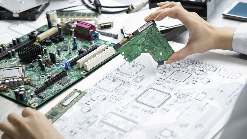
Assembly drawing
It is a drawing that shows the outline of the PCB along with all the elements on it.
It is necessary for assembler to properly identify the location of components.
Main recommendations for making a correct assembly drawing:
- recommended form: pdf or jpg,
- the drawing should include the description/designations/designator of elements, e.g. R1, R2, C1, Q1, etc. This should be done in accordance with other attached documentation, e.g. BOM,
- descriptions shall be placed next to elements, not in the middle, because then the drawing becomes unreadable,
- marking the direction of location for elements such as e.g. diodes or a microcontroller is necessary. For example marking the position of the first pin or diode polarization with a dot.,
- the inscriptions in the drawing should not be placed in a mirror image,
- drawings should be made separately for elements that are mounted at the top of the board and those at the bottom.
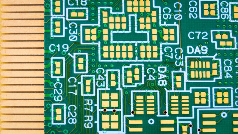
Pasta files
Usually created as Gerber format- thanks to them a stencil for the solder paste can be made and the SMD elements can be installed.
The main recommendations for the correct execution of those files:
- recommended format - GERBER,
- if you have PCB's in panel, please provide those files for the whole panel and not just for a single board,
- if the SMD assembly is to be made on both sides of the PCB, files should be provided separately for elements that are mounted at the top of the board and those at the bottom.
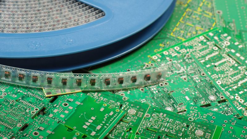
Pick and Place files (P&P)
Pick and Place are files intended for machines used for precise placement of SMD components on a PCB. Thanks to these files, the machine knows where, in what rotation and which element should be placed.
The main recommendations for proper execution of pick and place files:
- recommended format - Excel;
- designator of a given element. Each element must be listed separately with its value, casing and exact position on the board: x [mm] and y [mm] and layer. Optionally, you can add a comment.
If you have a problem with generating / creating production files, please contact us. Our technical department will be happy to answer all your questions.